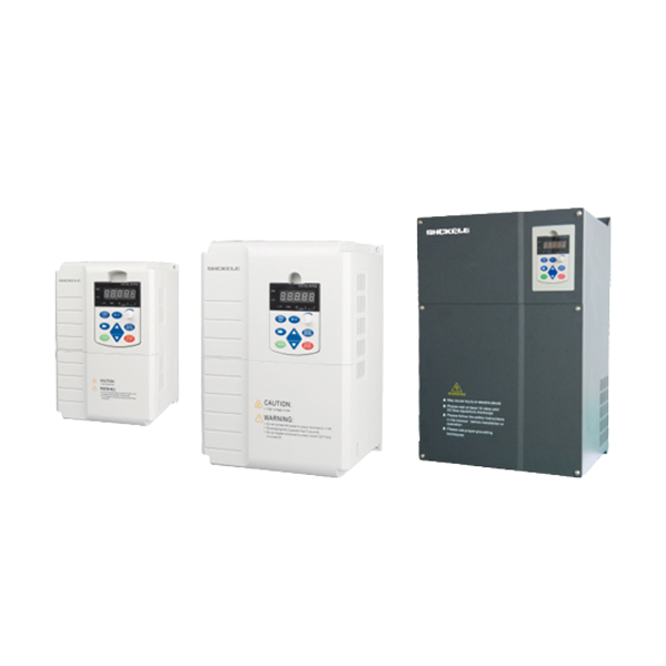
Products


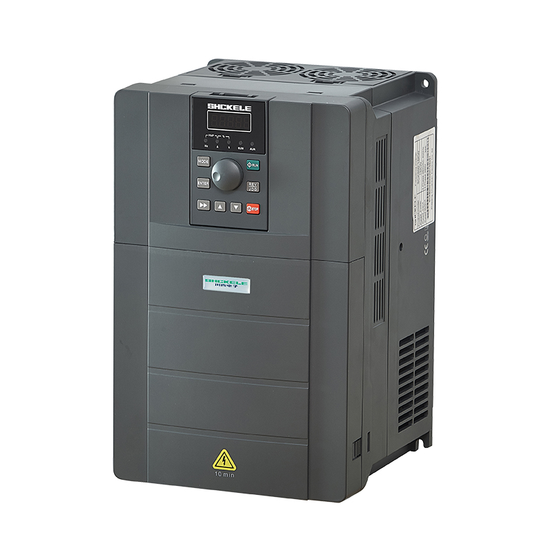
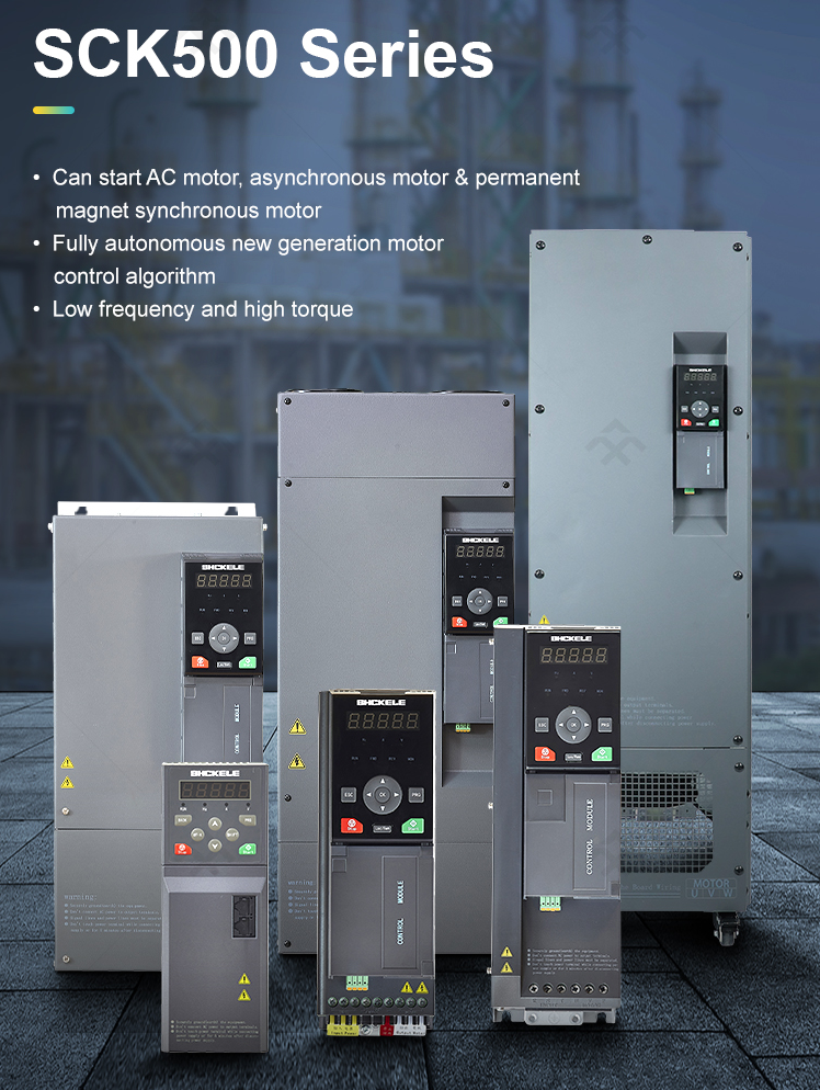
SCK500 series frequency inverter catalog
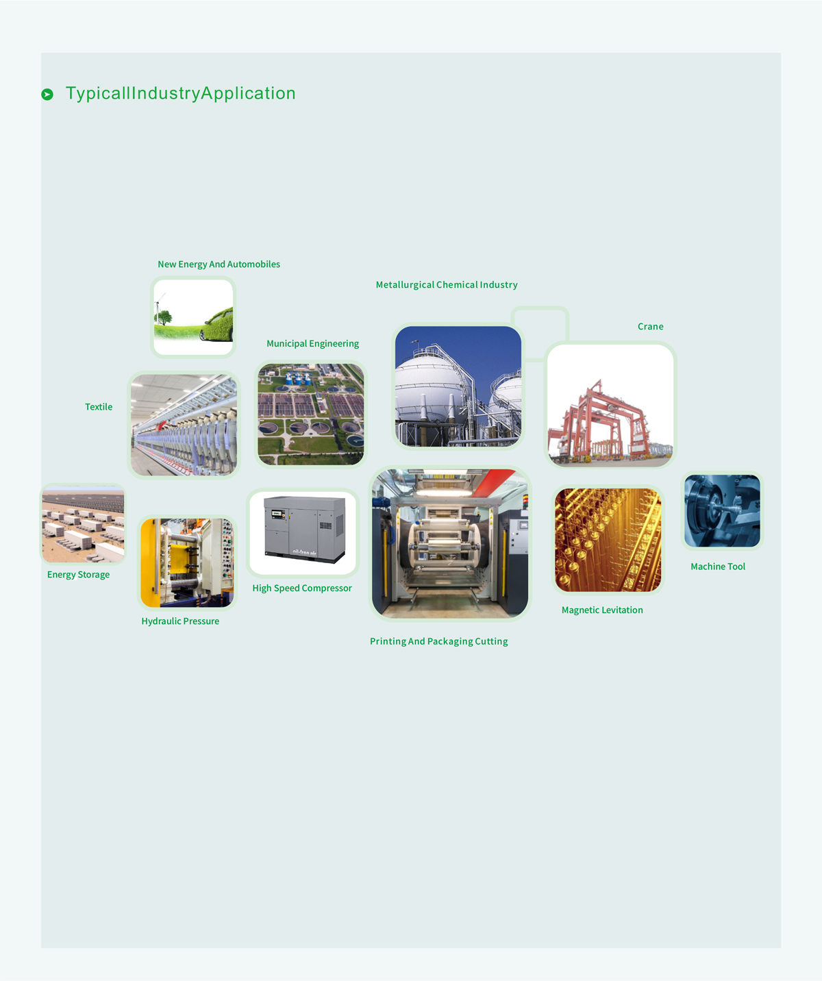
Application
Lifting,machine tools,plasticmachines,ceramics,glass,woodworking,centrifuges,food processing,textile equipment,printing bags, industrial washing machines and other fields
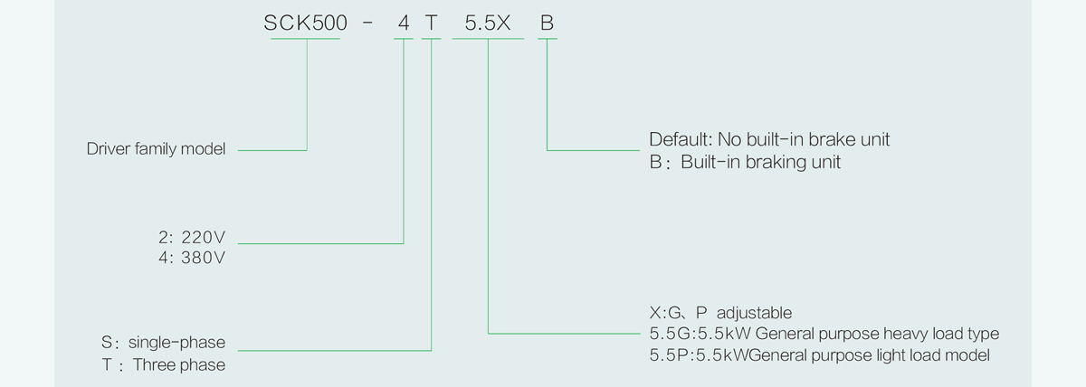
General Mode lInstruction
Overview
Voltage level:380V
Power class:1.5-710kW
●According to the European Union CE standard: EN61800-5-1 design
●Completely independent new generation of motor control algorithm, some high-end applications breakthrough European, American and Japanese brands monopoly
●Low frequency high torque, open loop 0.05Hz stable high torque output, help mechanical equipment field performance upgrade
●Fast dynamic response, fast acceleration and deceleration, to achieve multiple types of load better start and stop
●Precise flux following and optimization technology, to achieve more efficient motor operation
● Fast current limiting technology to ensure long running of the drive
●Modular design concept, high power density, save installation space
●Open loop vector control is comparable to closed loop vector control, high precision, high response
● Can drive all types of AC motor, asynchronous motor & permanent magnet synchronous motor & special motor
●160-710kW standard built-in DC reactor
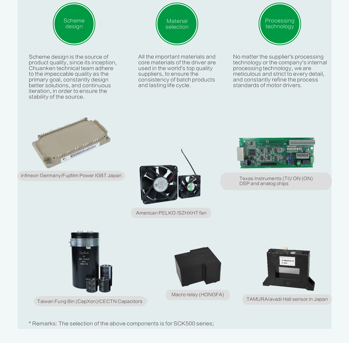
Product quality overview
Chuanken technical team regards product quality as the life of the enterprise, we should cherish and defend product quality as we cherish and defend life.
To provide customers with quality products as an important mission, adhere to the following principles and directions:
Models and specifications
| Project | Specification | ||||||||||||||||
| SCK500-4TXXXG(B) | 1.5 | 2.2 | 3.7 | 5.5 | 3.5 | 11 | 15 | 18.5 | 22 | 30 | 37 | 45 | 55 | 75 | 90 | 110 | |
| Adaptive motor power(kW) | 1.5 | 2.2 | 3.7 | 5.5 | 7.5 | l1 | 15 | 18.5 | 22 | 30 | 37 | 45 | 55 | 75 | 90 | 110 | |
| lntput | Rsted input current(A) | 4.5 | 6.3 | 11.4 | 16.7 | 21.9 | 32.2 | 1.3 | 19.5 | 59 | 57 | f9 | 89 | 10G | 139 | 151 | 196 |
| Output | Rated outputcurrent (A) | 3.8 | 5.1 | 9 | 13 | 17 | 24 | 32 | .37 | 45 | 60 | 75 | 90 | 112 | 150 | 180 | 210 |
| Output voltago | 3 Phaso 0V~ ratcd input voltagc | ||||||||||||||||
| laximum output frequency | 300.00Hz(Modifiable by pararmetery | ||||||||||||||||
| Carrier frequency | 1.0kHz~16.0kHz | ||||||||||||||||
| owerload capacity | 150%rated current 60s;180%rated current 10s;200%rated current 0.5s | ||||||||||||||||
| High frequency leakage curreit courtermeasures |
DCreactcr | External optional parts | Built-in optional | ||||||||||||||
| Braking function | Brake unit | Standard built-in | Built-in optional | ||||||||||||||
| Power supply | Rated voltage | AC:three phase 36oV~460V | |||||||||||||||
| Ratad fraquency | 50Hz/6OHz | ||||||||||||||||
| Allawable range of voltrige flicfuistiori |
-15% to 10%.Tho actual alowabla range isAC323V to 52HV | ||||||||||||||||
| Allowable range of froquchcy fiuctustion |
±5% | ||||||||||||||||
| Power supply capacity(kVA) | 5.0 | 6.7 | 12 | 17.5 | 22.8 | 33.4 | 42.8 | 45 | 54 | 52 | 63 | 81 | 97 | 127 | 150 | 179 | |
| Project | Specification | |||||||||||||||
| SCK500-4TXXXG(B) | 132 | 160 | 185 | 200 | 220 | 250 | 280 | 315 | 355 | 400 | 450 | 500 | 560 | 630 | 710 | |
| Adaptive motor power (kW) | 132 | 160 | 185 | 200 | 220 | 250 | 280 | 315 | 355 | 400 | 450 | 500 | 560 | 630 | 710 | |
| Intput | Ratad input current(A) | 240 | 287 | 326 | 365 | 410 | 441 | 495 | 555 | 617 | 687 | 782 | 835 | 920 | 1050 | 1180 |
| Output | Rated output current (A) | 260 | 305 | 350 | 377 | 426 | 465 | 520 | 585 | 650 | 725 | 810 | 900 | 1020 | 1100 | 1300 |
| Output voltage | 3 Phase ov-rated input voltage | |||||||||||||||
| Maximum output frequency | 300.00Hz(Modifiable by parameter) | |||||||||||||||
| carrier frequency | 1.0kHz~16.0kHz | 1.0kHz-8.0kHz | ||||||||||||||
| Overload capacity | 150% rated current 60s;180% rated current 10s;200% rated current 0.5s | |||||||||||||||
| High frequency leakage currcnt countermeasureg |
DGreactor | Built-in oplianal |
Standard built-in | |||||||||||||
| Braking function | Erake unit | Built in optional |
Externaloptional parts | |||||||||||||
| Power supply |
Rated voltage | AC:three phase 360V~460v | ||||||||||||||
| Rated frequency | 50Hz/60Hz | |||||||||||||||
| Allowable range of voltage fluctuatior |
-15% to 10%.The actual allowed range :AC 323V to 528V | |||||||||||||||
| Allowable range of frequency fuctuation |
±5% | |||||||||||||||
| Power supply capacity (kVA) | 220 | 263 | 304 | 334 | 375 | 404 | 453 | 517 | 565 | 629 | 716 | 769 | 861 | 969 | 1092 | |
Technical parameter
| Project | Specification | ||
| Basic function |
lnput frequency resolution |
Digital sotting :0.01Hz simulation setting:ifaximum speed x0.025% |
|
| Controll mode | Advanced scalar control PGfree wector controil (svc) You havePG vectorcontroil |
||
| starting torque | SVC:0.25Hz 150% VC:0.00Hz 180% |
||
| Speed range | SVC:1:200 | VC:1:100o | |
| Spced stability accuracy | SVC:±0.5% | VC:±0.2% | |
| Torque control accuracy | SVC:5Hz above±5% | VC:5Hz above±3% | |
| Torquereentry accuracy | ≤0.5% rated torque of motor | ||
| Torque response time | SVC:≤ 10ms(rated torque of motor) | VC:= 5ms(rated torque of motor) | |
| Torque ift | Automatic torque lifting function;Manual torque increase by0.1%-30.0% | ||
| V/F curve | Straight line, multiple power curve,multipoint curve,V/Fseparation | ||
| Deceleration curve | Straight line,polyline,s curve | ||
| DC braking | DC braking starting frequency:0.00-300.00Hz;Dc braking current: constant torque 0.0-120.0%;Variablo torque 0.0-90.0% Dc braking timo :0.0-30.0s;Fast braking without DC braking start waiting timo |
||
| Point control | Click frequency range :0.00Hz-50.00Hz lnching deceleration time range:o.0s- 3600.0s |
||
| Process cllosed- loopPD |
The closed-loop controlsystem can be realized conveniently | ||
| PLC, more simple instructions |
Up to 16segments of speed can be achieved by built-in simple PLC or x terminal easy | ||
| utomatic voltage regulation |
when the grid voltage fluctuates,the output voltage can be kept stable automatically | ||
| Over and over pressure stall control |
Automatic limit of current and voltage during operation to prevent frequent over voltage and over voltage tros to |
||
| Automatic fast current limiting |
Minimize overcurrent failure and protect the normal operation of the drive | ||
| Torque lmitation and control |
Tho "excavator" feature automatically limits torque during operation to prevent frequent overcurrent trips;Wnen vector control.torque control can be realized |
||
| Personalized function |
lnstantstop | Theload feedback energy is used to compensate for the voltage reduction in the transient outage and keep the driverrunning for ashort time |
|
| Fast currentlimiting | Avoid frequent overcurrent failure of the drive | ||
| Timing function | Therealization of driver timing control | ||
| Motor gxerheat | Motor tomperature detoction can be easily achioved by externalsensors | ||
| arameter copy | Canrealize the parameter upload,download,realize the parameter fastsetting | ||
| Double so Modbus | Dual notwork ports support Modbus for simple networking | ||
| Power-on short circuit detection |
Electricity automatically on short circuit detection | ||
| Flux braking | with the flux brake,it can achieve a fasterdeceleration stop | ||
| Project | Specification | |
| Run | Run instruction | Keyboard command, terminal command,communication command,multi-sogment command; Canbe switched in a variety of ways |
| Master spood instruction | 12main spoed instruction given modo,and can be switched through a variety of ways | |
| Auxiliary speedinstruction | 9 kinds of auxiliary speed instruction given way, can flexibly achieve auxiiary speed fine-tuning, speed synthesis |
|
| Input terminal | 7xterminals, one of which supports high-speed pulse input 3All terminals,1support0~10V voltage signals,2 support0~10V voltage signals or 0~ 20mA current signals 15v differential encoder interface |
|
| Output terminal | 2 relay outputs 2 transistor output,one of which supports high speed pulse output 2 AO outputs, both supparting 0~10v voltage signal or 0~ 20mA current signal |
|
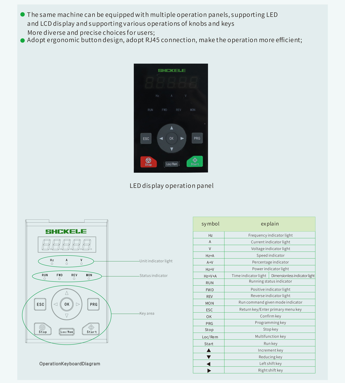
| Human- computer interaction |
LED display | LED keyboard |
| LCD display | LCD operating keyboard | |
| Key lock function | Realize all or part of the keyboard key lockfunction to prevent keyboard misoperation | |
| Keyboard emergency stop | Use the keyboard stop key to stop any command source and reduce operational risks | |
| Protection function |
Short circuit protection | Output phaseshort-circuit protoction,output short-circuit protoction to tho ground |
| Overcurrent protection | Stop protection in excess of2.2 timesrated drive current | |
| Overvoltage protection | Stop when the DC bus voltage of the main loop is greater than 80ov | |
| Undervoltage protection | Stop when the DC bus voltage of the main loop is less than 360v | |
| Overload protection | Stop 150%ratod current,run 60s stop |
|
| Overheat protection | Drive lGBT overheat protection | |
| Phase loss protection | Three-phase input phase protection, three-phase output phase protection | |
| Environment | Place of use | lndoor, free from direct sunlight, dust, corrosive gas,flammable gas, oil mist, water vapor, water droplets and salt |
| Altitude | No derating is needed below 1000m,Derating is 1% for every 100m rise above 1000m. The highest altitude is not more than 30oom |
|
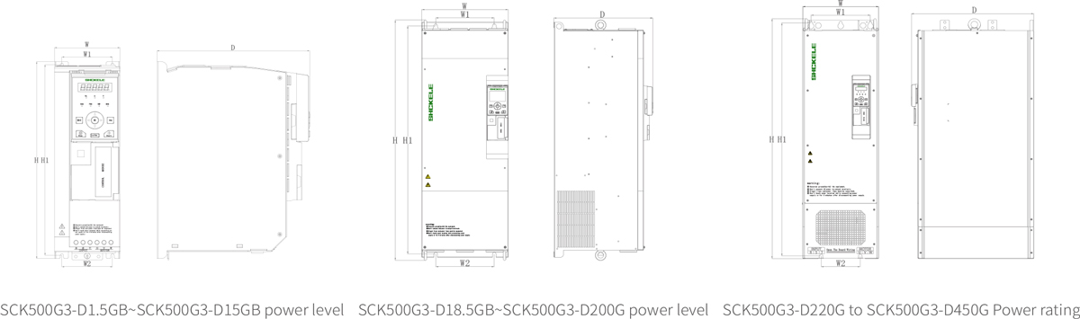
Shape and mounting dimensions
| Driver type | Profile and mounting size(mm) | |||||||
| W | H | D | W1 | W2 | H1 | Mounting aperture |
Reactor | |
| SCK500-4T1.5GB | 81 | 237 | 173 | 67.5 | 57 | 57224.5 | 4.5 | |
| SCK500-4T2.2GB | ||||||||
| SCK500-4T3.7GB | ||||||||
| SCK500-4T5.5GB | ||||||||
| SCK500-4T7.5GB | 95 | 297 | 222 | 73.5 | 73.5 | 287.5 | 6 | |
| SCK500-4T11GB | ||||||||
| SCK500-4T15GB | ||||||||
| SCK500-4T18.5GB | 185 | 440 | 249 | 140 | 140 | 427.5 | 7 | Matching |
| SCK500-4T22GB | ||||||||
| SCK500-4T30GB | ||||||||
| SCK500-4T37G | 239 | 604.5 | 269.5 | 180 | 148.5 | 580 | 9.5 | |
| SCK500-4T45G | ||||||||
| SCK500-4T55G | 265 | 690 | 323 | 200 | 200 | 674 | 9.5 | |
| SCK500-4T75G | ||||||||
| SCK500-4T90G | 295 | 833.5 | 338.5 | 200 | 200 | 810 | 12 | |
| SCK500-4T110G | ||||||||
| SCK500-4T132G | ||||||||
| SCK500-4T160G | 350 | 1070 | 407 | 265 | 265 | 1046.5 | 14 | |
| SCK500-4T185G | ||||||||
| SCK500-4T200G | ||||||||
| SCK500-4T220G | 339 | 1104.5 | 498 | 265 | 175 | 1081.5 | 14 | |
| SCK500-4T250G | ||||||||
| SCK500-4T280G | ||||||||
| SCK500-4T315G | 660 | 1339.5 Note:1339.5 in cludes Base 350 |
392 | 600 | 550 | 1312 Note:1312 includesBase35o |
14 | Standard built-in |
| SCK500-4T355G | ||||||||
| SCK500-4T400G | ||||||||
| SCK500-4T450G | ||||||||
| SCK500-4T500G | ’850 | 1600 | 600 | - | - | - | 16 | |
| SCK500-4T560G | ||||||||
| SCK500-4T630G | ||||||||
| SCK500-4T710G | ||||||||
Attached :315kW-450kW book size
| Drivertype | Profile and mounting size (mm) | |||||||
| W | H | D . | W1 | W2 | H1 | Mounting aperture |
Reactor | |
| SCK500-4T315G | 339 | 1300 | 546.5 | 265 | 175 | 1267.5 | 16 | Standard built-in |
| SCK500-4T355G | ||||||||
| SCK50O-4T400G | ||||||||
| SCK50O-4T450G | ||||||||
SCK500 series peripheral device selection, terminal screw and wiring specifications
| Driver type | Circuit breaker (A) |
Contactor (A) |
Powerterminal | Ground terminal | ||||
| Screw | Tightening moment (N.m) |
Cable specification (mm²) |
Screw | Tightening moment (N.m) |
Cable specification (mm²) |
|||
| SCK500-4T1.5GB | 10 | 9 | M4 | 1.2~1.5 | 2.5 | M3 | 0.5~0.6 | 2.5 |
| SCK500-4T2.2GB | 16 | 12 | M4 | 1.2~1.5 | 2.5 | M3 | 0.5~0.6 | 2.5 |
| SCK500-4T3.7GB | 20 | 18 | M4 | 1.2~1.5 | 4 | M3 | 0.5~0.6 | 4 |
| SCK500-4T5.5G8 | 32 | 32 | M5 | 2.5~3.0 | 4 | M5 | 2.5~3.0 | 4 |
| SCK500-4T7.5GB | 32 | 32 | M5 | 2.5~3.0 | 6 | M5 | 2.5~3.0 | 6 |
| SCK500-4T11GB | 50 | 50 | M5 | 2.5~3.0 | 6 | M5 | 2.5~3.0 | 6 |
| SCK500-4T15GB | 63 | 50 | M5 | 2.5~3.0 | 6 | M5 | 2.5~3.0 | 6 |
| SCK500-4T18.5GB | 80 | 65 | M6 | 4.0~5.0 | 10 | M6 | 4.0~5.0 | 10 |
| SCK500-4T22GB | 100 | 8o | M6 | 4.0~5.0 | 16 | M6 | 4.0~5.0 | 16 |
| SCK500-4T30GB | 125 | 95 | M6 | 4.0~5.0 | 25 | M6 | 4.0一5.0 | 16 |
| SCK500-4T37G | 160 | 125 | M8 | 9.0~10.0 | 25 | M8 | 9.0~10.0 | 16 |
| SCK500-4T45G | 200 | 150 | M8 | 9.0~10.0 | 35 | M8 | 9.0~10.0 | 16 |
| SCK500-4T55G | 225 | 185 | M8 | 9.0~10.0 | 50 | M8 | 9.0~10.0 | 25 |
| SCK500-4T75G | 250 | 225 | M10 | 17.6~22.5 | 60 | M8 | 9.0~10.0 | 35 |
| SCK500-4T90G | 315 | 265 | M10 | 17.6~22.5 | 70 | M8 | 9.0~10.0 | 35 |
| SCK500-4T110G | 350 | 330 | M10 | 17.6~22.5 | 100 | M8 | 9.0~10.0 | 50 |
| SCK500-4T132G | 400 | 400 | 10 | 17.6~22.5 | 120 | M8 | 9.0~10.0 | 70 |
| SCK500-4T160G | 500 | 400 | M12 | 31.4~39.2 | 150 | M12 | 31.4~39.2 | 95 |
| SCK500-4T185G | 500 | 500 | M12 | 31.4~39,2 | 150 | M12 | 31.4~39.2 | 95 |
| SCK500-4T200G | 630 | 500 | M12 | 31.4~39.2 | 185 | M12 | 31.4~39.2 | 95 |
| SCK500-4T220G | 630 | 630 | M12 | 31.4~39.2 | 185 | M12 | 31.4~39,2 | 120 |
| SCK500-4T250G | 800 | 630 | M12 | 31.4~39.2 | 120×2 | M12 | 31.4~39.2 | 120 |
| SCK500-4T280G | 800 | 80o | M12 | 31.4~39,2 | 150×2 | M12 | 31.4~39.2 | 150 |
| SCK500-4T315G | 800 | 80o | M12 | 31.4~39,2 | 185×2 | M12 | 31.4~39,2 | 95×2 |
| SCK500-4T355G | 1000 | 800 | M12 | 31.4~39.2 | 240×2 | M12 | 31.4~39.2 | 120×2 |
| SCK500-4T400G | 1250 | 1000 | M12 | 31.4~39,2 | 240×2 | M12 | 31.4~39.2 | 120×2 |
| SCK500-4T450G | 1250 | 1000 | M12 | 31.4~39,2 | 300×2 | M12 | 31.4~39.2 | 150×2 |
| SCK500-4T500G | 1600 | 1250 | M12 | 31.4~39,2 | 300×2 | M12 | 31.4~39.2 | 150×2 |
| SCK500-4T560G | 1600 | 1250 | M12 | 31.4~39.2 | 400×2 | M12 | 31.4~39.2 | 185×2 |
| SCK500-4T630G | 2000 | 1600 | M12 | 31.4~39,2 | 400×2 | M12 | 31.4~39.2 | 185×2 |
| SCK500-4T710G | 2000 | 1600 | M12 | 31.4~39,2 | 400×2 | M12 | 31.4~39.2 | 185×2 |
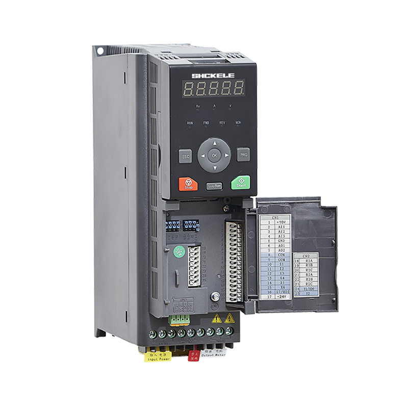
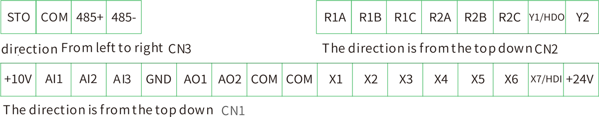
Standard wiring diagram
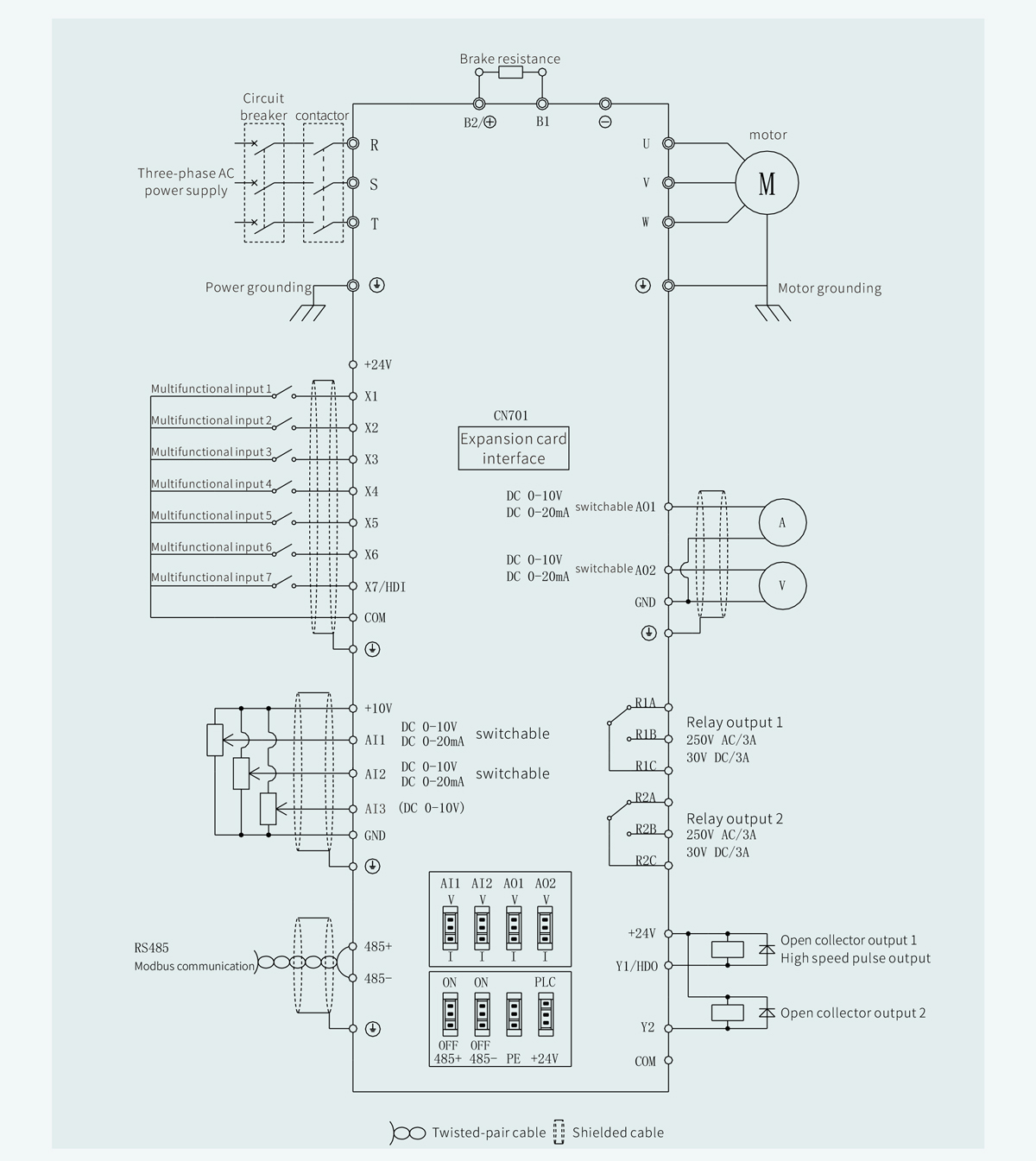
Control terminal position and function
| Analog input |
+10v | Analog input reference voltage |
10 V±1%,isolated fromCoMinternally |
| Maximumoutput current 20mA | |||
| GND | simulated ly | lnternal isolationfrom COM | |
| Al1/Al2 | Analog input channel 1/2 | 010V: lnput impedance22kQ | |
| 0 to 20mA: lnput impedance 5002 | |||
| Thejumperterminalcanswitch betweeno~ 10V ando~ 20mA analoginput,and thefactory default voltage input |
|||
| Analog output |
AI3 | Simulates input channel3 | 0~ 10V: Input impedance22 kΩ |
| AO1/AO2 | Analogoutput 1/2 | 0~ 10V: lmpedance ≥10 KΩ | |
| 0~ 20mA:The impedance rangesfrom200n~500Ω | |||
| Throughthej umperterminalto achieveo~ 10V and 0~ 20mA analogoutput switching,factory default voltage output |
|||
| GND | Simulatedly | lnternal isolationfrom COM | |
| +24v | +24V | 24V±20%, internally isolated fromGND | |
| Maximum load 200mA | |||
| COM | Plus 24V ground | lnternal isolation fromGND | |
| Digital input |
X1~X7 | Multifunctionalinput terminals 1to7 |
lnput specifications :24V DC,5mA Frequency range :0 to 200Hz voltage range :24V±20% |
| X7/HDI | Multifunctional input/pulse input |
Multifunctionalinput:same asx1 toX7 | |
| PULse input :0.1Hz~50kHz;Voltage range :24V±20% | |||
| Digita output |
Y1/HDO | Opencollect oroutput | Opencollector output :1,voltage range :0~ 24V;2,current range :0~50mA |
| / pulse output | Puke output :0~50kHz | ||
| Y2 | Open collector out put | Opencollectoroutput:1,voltage range :0~24V;2,current range :0~50mA | |
| COM | Opencollector out put common end | lnternal isolationfromGND | |
| Relay 1 output |
R1A/R1B/R1C | Relay output 1 | R1b-r1c:Normally on |
| Rla-r1c:Normally closed | |||
| Contact capacity :250VAC/3A,30V DC/3A | |||
| Relay 2 output |
R2A/R2B/R2C | Relay output2 | R2Bto R2C:Normally enabled |
| R2A-R2C:Normally closed | |||
| Contact capacity :250VAC/3A,30V DC/3A | |||
| Terminal ST0/485 |
STO | Safety torque off | Whenthe STO is activated,the motor is ina stationary state,which can prevent the stationary motorfrom starting accidentally. whenthe STO is acthated,the motor is rotating and continues to rotate by inertia untilit comesto rest.lf the motorhas a lock brake,the lock brake closes immediately. |
| COM | Safe torque turrs off thecommonend | lnternal isolationfromGND | |
| 485+ | 485 Differentialsignal positive | Rate:4800/96o0/19200/38400/57600/115200 BpS | |
| 485 | 485 Differentialsignal negatve | longest distance of500 meters,withastandard oftwisted-pairshielded cable) | |
| Expansion card interface |
CN701 | Expansioncard inte rface |
Three optional operating panels
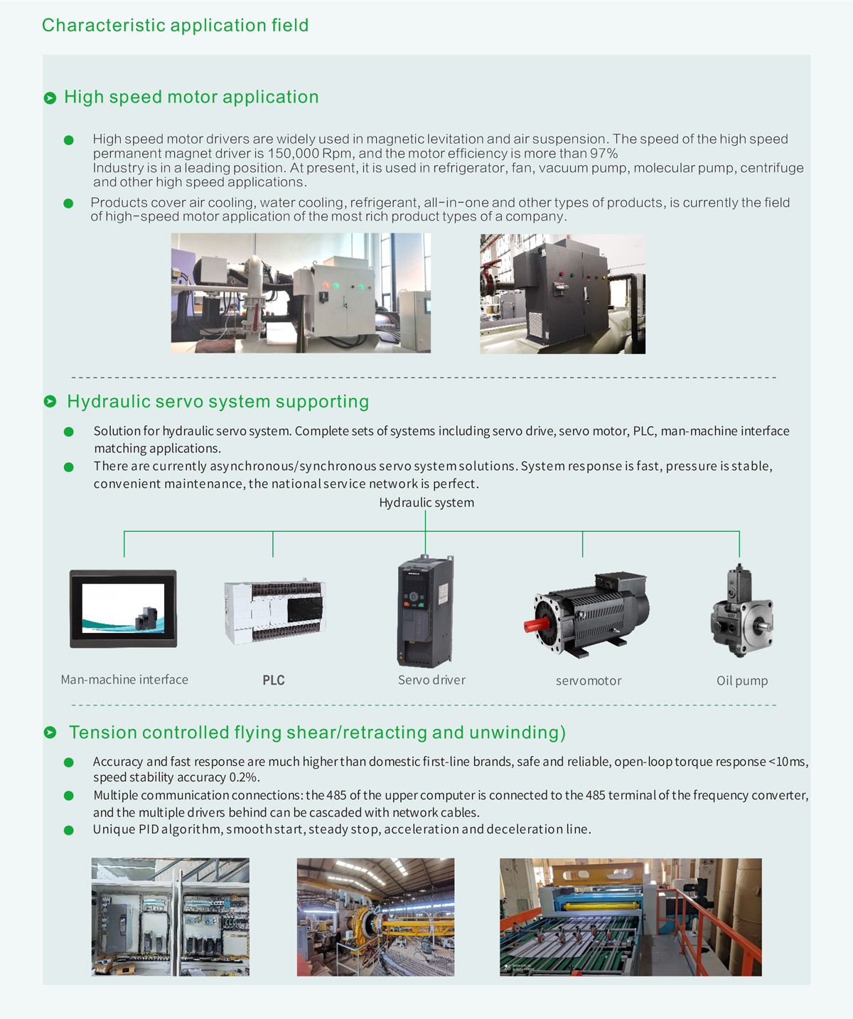
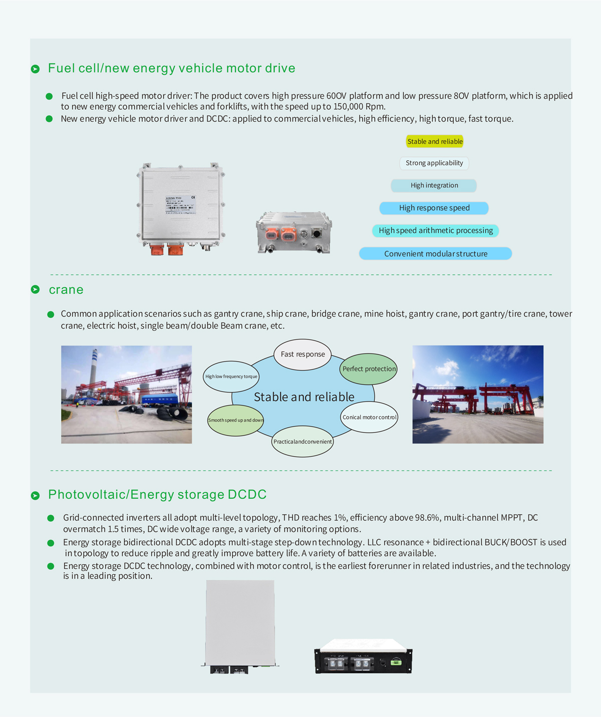
Characteristic application field