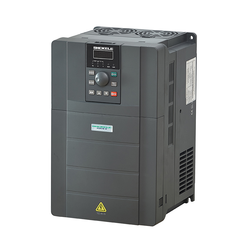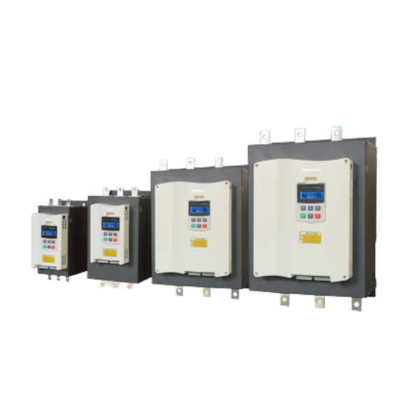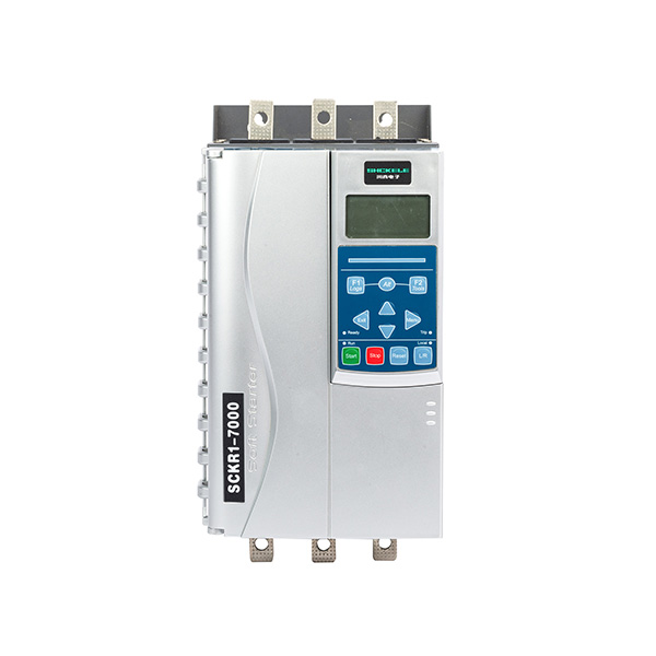
Products


Built in bypass type intelligent motor soft starter/cabinet
Risk of electric shock
There is voltage at the following positions, which may cause serious electric shock accidents and can be fatal:
● AC power cord and connection
● Output wires and connections
● Many components of starters and external optional equipment
Before opening the starter cover or performing any maintenance work, the AC power supply must be isolated from the starter with an approved isolating device.
Warning-risk of electric shock
As long as the supply voltage is connected (including when the starter is tripped or waiting for a command), the bus and the heat sink must be considered live.
Short circuit
Cannot prevent short circuit. After a severe overload or short circuit occurs, an authorized service agent should fully test the soft start working conditions.
Grounding and branch circuit protection
The user or installer must provide proper grounding and branch circuit protection in accordance with the requirements of local electrical safety regulations.
For safety
● The stop function of the soft start does not isolate the dangerous voltage at the output of the starter. Before touching the electrical connection, the soft starter must be disconnected with an approved electrical isolation device.
● The soft start protection function is only applicable to motor protection. The user must ensure the safety of machine operators.
● In some installation situations, accidental starting of the machine may endanger the safety of machine operators and may damage the machine. In such cases, it is recommended that you install an isolating switch and circuit breaker (such as a power contractor) that can be controlled by an external safety system (such as emergency stop and fault detection period) on the soft starter power supply.
● The soft starter has a built-in protection mechanism, and the starter trips when a fault occurs to stop the motor. Voltage fluctuations, power outages and motor jams can also cause the
motor to trip.
● After eliminating the cause of the shutdown, the motor may restart, which may endanger the safety of some machines or equipment. In this case, proper configuration must be made to prevent the motor from restarting after an unexpected shutdown.
● The soft start is a well-designed component that can be integrated into the electrical system; the system designer/user must ensure that the electrical system is safe and meets the requirements of the corresponding local safety standards.
● If you do not comply with the above recommendations, our company will not bear any responsibility for any damage caused thereby.
Appearance and installation dimensions of the built-in bypass intelligent motor soft starter

| Specification model | Dimensions (mm) | Installation size (mm) | |||||
|
W1 |
H1 |
D |
W2 |
H2 |
H3 |
D2 |
|
| 0.37-15KW |
55 |
162 |
157 |
45 |
138 |
151.5 |
M4 |
| 18-37KW |
105 |
250 |
160 |
80 |
236 |
M6 |
|
| 45-75KW |
136 |
300 |
180 |
95 |
281 |
M6 |
|
| 90-115KW |
210.5 |
390 |
215 |
156.5 |
372 |
M6 |
|
This soft starter is an advanced digital soft start solution suitable for motors with power ranging from 0.37kW to 115k. Provides a complete set of comprehensive motor and system protection functions, ensuring reliable performance even in the harshest installation environments.
Function list
Optional soft start curve
●Voltage ramp start
●Torque start
Optional soft stop curve
●Free parking
●Timed soft parking
Expanded input and output options
● Remote control input
● Relay output
● RS485 communication output
Easy to read display with comprehensive feedback
●Removable operation panel
●Built-in Chinese + English display
Customizable protection
●Input phase loss
●Output phase loss
●Running overload
●Starting overcurrent
●Running overcurrent
●Underload
Models that meet all connectivity requirements
● 0.37-115KW (rated)
● 220VAC-380VAC
●Star shaped connection
or inner triangle connection
Instructions for External Terminals of Built in Bypass Intelligent Motor Soft Start

| Terminal type |
Terminal No. |
Terminal name |
Instruction | |
|
Main circuit |
R,S,T |
Power Input |
Soft start three-phase AC power input | |
|
U,V,W |
Soft Start Output |
Connect three-phase asynchronous motor | ||
|
Control loop |
Communication |
A |
RS485+ |
For ModBusRTU communication |
|
B |
RS485- |
|||
|
Digital input |
12V |
Public |
12V common | |
|
IN1 |
start |
Short connection with common terminal (12V) Startable soft start | ||
|
IN2 |
Stop |
Disconnect from the common terminal (12V) to stop the start soft start | ||
|
IN3 |
External Fault |
Short-circuit with the common terminal (12V)
, soft start and shutdown |
||
| Soft start power supply |
A1 |
AC200V |
AC200V output | |
|
A2 |
||||
|
Programming Relay 1 |
TA |
Programming relay common |
Programmable output, available fromChoose from the following functions:
|
|
|
TB |
Programming relay normally closed |
|||
|
TC |
Programming relay normally open |
|||
Operation Panel

|
key |
function |
|
Start |
starter |
|
STOP/RST |
|
|
ESC |
Exit menu/submenu |
 |
|
 |
|
 |
|
|
SET/Enter |
|
|
Fault light |
|
Starter status LED
| name |
Light |
flicker |
| run | The motor is in a starting, running, soft stop, and DC braking state. | |
| trippingoperation | The starter is in a warning/ tripping state |
The local LED light only works for keyboard control mode. When the light is on, it indicates that the panel can start and stop. When the light is off, the meterThe display panel cannot be started or stopped.
Basic Parameters
|
function |
|||
| number |
function name |
set range |
Modbus address |
|
F00 |
Soft start rated current |
Motor rated current |
0 |
| Description: The rated working current of the soft starter should not exceed the working current of the matching motor [F00] | |||
|
F01 |
Motor rated current |
Motor rated current |
2 |
| Description: The rated working current of the motor in use should be consistent with the current displayed in the bottom right corner of the screen | |||
|
F02 |
control mode |
0: Prohibit start stop
1: Individual keyboard control 2: External control is individually controlled 3: Keyboard+external control 4: Separate communication control 5: Keyboard+Communication 6: External control+ communication 7: Keyboard+external control +communication |
3 |
Description: This determines which methods or combinations of methods can control soft start.
|
|||
|
F03 |
Starting method 000000 |
0: Voltage ramp start
1: Limited current starting |
4 |
| Description: When this option is selected, the soft starter will quickly increase voltage from [35%] to [rated voltage] * [F05], and then gradually increase voltage. Within [F06] time, it will increase to [rated voltage]. If the startup time exceeds [F06]+5 seconds and the startup is still not completed, a startup timeout will
be reported |
|||
|
F04 |
Starting current limiting percentage | 50%~600%
50%~600% |
5 |
| Description: The soft starter will gradually increase voltage starting from [rated voltage] * [F05], as long as the current does not exceed [F01] * [F04], will be continuously boosted to [rated voltage] | |||
|
F05 |
Starting voltage percentage |
30%~80% |
6 |
| Description: The [F03-1] and [F03-2] soft starters will gradually increase voltage starting from [rated voltage] * [F05] | |||
|
F06 |
START time |
1s~120s |
7 |
| Description: The soft starter completes the step up from [rated voltage] * [F05] to [rated voltage] within [F06] time | |||
| F07 |
Soft stop time |
0s~60s |
8 |
| Soft start voltage drops from [rated voltage] to [0] within [F07] time | |||
|
F08 |
Programmable relay 1 |
0: No action
1: Power on action 2: Soft start middle action 3: Bypass action 4: Soft stop action 5: Running actions 6: Standby action 7: Fault action |
9 |
| Description: Under what circumstances can programmable relays switch | |||
|
F09 |
Relay 1 delay |
0~600s |
10 |
| Description: Programmable relays complete switching after triggering the switching condition and passing through【F09】 time | |||
| F10 | mail address |
1~127 |
11 |
| Description: When using 485 communication control, the local address. | |||
| F11 | Baud rate |
0:2400 1:4800 2:9600 3:19200 |
12 |
| Description: The frequency of communication when using communication control | |||
|
F12 |
Operating overload level |
1~30 |
13 |
| Description: The curve number of the relationship between the magnitude of overload current and the time to trigger overload tripping and shutdown, as shown in Figure 1 | |||
|
F13 |
Starting overcurrent multiple |
50%-600% |
14 |
| Description: During the soft start process, if the actual current exceeds [F01]
* [F13], the timer will start. If the continuous duration exceeds [F14], the soft starter will trip and report [starting overcurrent] |
|||
|
F14 |
Start overcurrent protection time |
0s-120s |
15 |
| Description: During the soft start process, if the actual current exceeds [F01] * [F13], the timer will start. If the continuous duration exceeds [F14]
, the soft starter will trip and report [starting overcurrent] |
|||
|
F15 |
Operating overcurrent multiple |
50%-600% |
16 |
| Description: During operation, if the actual current exceeds [F01] * [F15]
, timing will begin. If it continues to exceed [F16], the soft starter will trip and report [running overcurrent] |
|||
|
F16 |
Running overcurrent protection time |
0s-6000s |
17 |
| Description: During operation, if the actual current exceeds [F01] * [F15]
, timing will begin. If it continues to exceed [F16], the soft starter will trip and report [running overcurrent] |
|||
|
F17 |
Three-phase unbalance |
20%~100% |
18 |
| Description: Timing starts when [three-phase maximum value]/[three-phase mean value] -1>[F17], lasting for more than [F18], soft starter tripped and reported [three-phase imbalance] | |||
|
F18 |
Three phase imbalance protection time |
0s~120s |
19 |
| Description: When the ratio between any two phases in the three-phase current is lower than [F17], timing begins, lasting for more than [F18], soft starter tripped and reported [three-phase imbalance] | |||
| number | function name |
set range |
Modbus address |
|
|
F19 |
Underload protection multiple |
10%~100% |
20 |
|
| Description: When the ratio between any two phases in the three-phase current is lower than [F17], timing begins, lasting for more than [F18], soft starter tripped and reported [three-phase imbalance] | ||||
|
F20 |
Underload protection time |
1s~300s |
21 |
|
| Description: When the actual current is lower than [F01] * [F19] after starting
, timing starts. If the duration exceeds [F20], the soft starter trips and reports [motor under load] |
||||
| F21 | A-phase current calibration value |
10%~1000% |
22 |
|
| Description: [Display Current] will be calibrated to [Original Display Current] * [F21] | ||||
| F22 | B-phase current calibration value |
10%~1000% |
23 |
|
| Description: [Display Current] will be calibrated to [Original Display Current] * [F21] | ||||
| F23 | C-phase current calibration value |
10%~1000% |
24 |
|
| Description: [Display Current] will be calibrated to [Original Display Current] * [F21] | ||||
| F24 | Operation overload protection |
0: Trip stop 1: Ignored |
25 |
|
| Description: Is the trip triggered when the operating overload condition is met | ||||
| F25 | Starting overcurrent protection |
0: Trip stop 1: Ignored |
26 |
|
| Description: Is the trip triggered when the [start overcurrent] condition is met | ||||
| F26 | Operation overcurrent protection |
0: Trip stop 1: Ignored |
27 |
|
| Description: Is the trip triggered when the operating overcurrent condition is met | ||||
| F27 | Three-phase imbalance protection |
0: Trip stop 1: Ignored |
28 |
|
| Description: Is the trip triggered when the three-phase imbalance condition is met | ||||
| F28 | Underload protection |
0: Trip stop 1: Ignored |
29 |
|
| Description: Is the trip triggered when the motor under load condition is met | ||||
| F29 | Output phase loss protection |
0: Trip stop 1: Ignored |
30 |
|
| Description: Is the trip triggered when the [output phase loss] condition is met | ||||
| F30 | Thyristor breakdown protection |
0: Trip stop 1: Ignored |
31 |
|
| Description: Is the trip triggered when the conditions for the thyristor are met | ||||
| F31 | Soft start operation language |
0: English 1: Chinese |
32 |
|
| Description: Which language is selected as the operating language | ||||
|
F32 |
Selection of water pump matching equipment |
0: None
1: Floating ball 2: Electric contact pressure gauge 3: Water supply level relay 4: Drainage liquid level relay |
33 |
|
| Description: See Figure 2 | ||||
|
F33 |
Running a Simulation |
- |
||
| Description: When starting the simulation program, be sure to disconnect the main circuit | ||||
|
F34 |
Dual display mode | 0: Local control valid 1: Local control invalid | ||
| Description: Is the operation of soft lifting the display screen on the body effective when inserting an additional display screen | ||||
| F35 |
Parameter lock password |
0~65535 |
35 |
| F36 |
Accumulated running time |
0-65535h |
36 |
| Description: How long has the software started running cumulatively | |||
| F37 |
Accumulated number of starts |
0-65535 |
37 |
| Description: How many times has the soft start been run cumulatively | |||
| F38 |
Password |
0-65535 |
- |
| F39 |
Main control software version |
99 |
|
| Description: Display the version of the main control software | |||
|
state |
|||
|
number |
function name |
set range |
Modbus address |
|
1 |
Soft start state |
0: standby 1: Soft rise
2: Running 3: Soft stop 5: Fault |
100 |
|
2 |
Current Fault |
0: No malfunction 1: Input phase loss
2: Output phase loss 3: Running overload 4: Running overcurrent 5: Starting overcurrent 6: Soft start under load 7: Current imbalance 8: External faults 9: Thyristor breakdown 10: Start timeout 11: Internal fault 12: Unknown fault |
101 |
|
3 |
Output current |
102 |
|
|
4 |
spare |
103 |
|
|
5 |
A-phase current |
104 |
|
|
6 |
B-phase current |
105 |
|
|
7 |
C-phase current |
106 |
|
|
8 |
Start completion percentage |
107 |
|
|
9 |
Three-phase imbalance |
108 |
|
|
10 |
Power frequency |
109 |
|
|
11 |
Power phase sequence |
110 |
|
|
Operate |
|||
|
number |
Operation Name | types of |
Modbus address |
|
1 |
Start stop command |
0x0001 Start 0x0002 reserved 0x0003 Stop 0x0004 Fault reset |
406
|
| Selection of supporting functions for water pumps | |||
| ① | 0: None | No: Standard soft start function. |
As shown in Figure |
| ② | 1: Floating ball | Float: IN1, close to start, open to stop. IN2 has no function. |
As shown in Figure |
| ③ | 2: Electric contact pressure gauge | Electric contact pressure gauge: IN1 starts when closed
, IN2 stops when closed. |
As shown in Figure |
| ④ | 3: Water supply level relay | Water supply level relay: IN1 and IN2 both open and start, IN1 and IN2 both close and stop. |
As shown in Figure |
| ⑤ | 4: Drainage liquid level relay | Drain liquid level relay: IN1 and IN2 both open and stop
, IN1 and IN2 both close and start. |
As shown in Figure |
Note: The water supply function starts and stops controlled by IN3, the standard soft start IN3 is an external fault, and the water supply type is used to control the start and stop. IN3 is the starting end, and the above operation can be performed only when it is closed, and it stops when it is open.

Troubleshooting
Protection response
When a protection condition is detected, the soft start writes the protection condition into the program, which may trip or cause Issue a warning. The soft start response depends on the protection level.
Users cannot adjust some of the protection responses. These trips are usually caused by external events (such as phase loss) It may also be caused by internal faults in the soft start. These trips have no relevant parameters and cannot be set as warnings orIgnored.
If The Soft Start Trips, You Need To Identify And Clear The Conditions That Triggered The Trip, Reset The Soft Start, And Then Proceed Restart. To Reset The Starter, Press The (stop/reset) Button On The Control Panel.
Trip messages
The following table lists the protection mechanisms and possible tripping reasons for soft start. Some settings can be adjusted with protection level
, while others are built-in system protection and cannot be set or adjusted.
| Serial Number | Fault name | Possible reasons | Suggested handling method | notes |
|
01 |
Input phase loss |
, and one or more phases of the soft start are not powered on.
|
This trip is not adjustable |
|
|
02 |
Output phase loss |
|
Related parameters : F29 |
|
|
03 |
Running overload |
|
|
Related parameters : F12, F24 |
| Serial Number | Fault name | Possible reasons | Suggested handling method | notes |
|
04 |
Underload |
|
1. Adjust parameters. |
Related parameters: F19,F20,F28 |
|
05 |
Running overcurrent |
|
|
Related parameters: F15,F16,F26 |
|
06 |
Starting overcurrent |
|
|
Related parameters: F13,F14,F25 |
|
07 |
External faults |
1. External fault terminalhas input. |
1. Check if there is input from the externalterminals. |
Related parameters : None |
|
08 |
Thyristor breakdown |
|
|
Related parameters : None |
Function Description
Overload protection
Overload protection adopts inverse time limit control

Among them: t represents the action time, Tp represents the protection level,
I represents the operating current, and Ip represents the rated current of the motor Characteristic curve of motor overload protection: Figure 11-1

Motor overload protection characteristics
| overload multiple
overload level |
1.05Ie |
1.2Ie |
1.5Ie |
2Ie |
3Ie | 4Ie | 5Ie |
6Ie |
|
1 |
∞ |
79.5s |
28s |
11.7s |
4.4s | 2.3s | 1.5s |
1s |
|
2 |
∞ |
159s |
56s |
23.3s |
8.8s | 4.7s | 2.9s |
2s |
|
5 |
∞ |
398s |
140s |
58.3s |
22s | 11.7s | 7.3s |
5s |
|
10 |
∞ |
795.5s |
280s |
117s |
43.8s | 23.3s | 14.6s |
10s |
|
20 |
∞ |
1591s |
560s |
233s |
87.5s | 46.7s | 29.2s |
20s |
|
30 |
∞ |
2386s |
840s |
350s |
131s | 70s | 43.8s |
30s |
∞:Indicates no action